
Stepper Motors can be accurately positioned due to the fact that they move in
'steps' not just on or off like a DC motor.
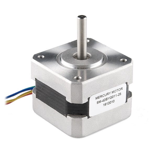
Here we use the L298N prefabricated board to control a bipolar stepper motor.
We have created a mount for the motor which you can download from Github here
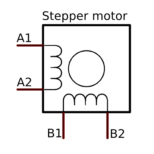
NOTE: You don't have to use this specific motor for the tutorial although it does need to be a bipolar stepper motor as seen in the diagram:
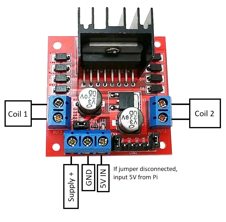
1. Firstly, we need to wire up the LM298N to the Raspberry Pi via some GPIO pins.
There is a 5V line out/in highlighted in the diagram below which is toggled using the highlighted jumper. It can output 5V when the jumper is connected but the board requires 5V to be fed in if the jumper is not connected. The jumper should only be connected when the supply voltage is less than 12V as the 5V regulator can only handle this voltage When the jumper is on, 5V should not be connected to the 5V port as the circuit regulates the supply voltage to 5V.
2. Next, identify the wires corresponding to each coil. Using the ohmmeter function on a multimeter, we can identify which wires are in a pair as they will have a resistance of under 100Ω usually. Wires that are not in a pair won't conduct.
3. Connect one pair of wires to the OUT1 terminal block, and the other pair to OUT2. The polarity of the coils doesn't matter.
4. Connect your power supply (maximum 35V) to the +12V rail and the GND port.
5. Download the basic program below which will simply rotate the motor 360° and then rotate back 360° with a delay of 2 seconds. You can download it using the following command or copy and paste the code below.
$ - wget "https://raw.githubusercontent.com/fraser148/pi-project-files/master/stepper_motor_basic.py"
#Projects4Pi.com

#Import libraries

import time

import RPi.GPIO as io


io.setwarnings(False)


#Declare output pins


io.setmode(io.BCM)

out1 = 4

out2 = 17

out3 = 27

out4 = 22

outputs = (out1,out2,out3,out4)


time_delay = 0.005


#Setup outputs


for out in outputs:

	io.setup(out,io.OUT)

	io.output(out,0)


#Define each step using sub-procedures


def step1():

	io.output(out1,0)

	io.output(out2,1)

	io.output(out3,1)

	io.output(out4,0)

	time.sleep(time_delay)


def step2():

	io.output(out1,0)

	io.output(out2,1)

	io.output(out3,0)

	io.output(out4,1)

	time.sleep(time_delay)


def step3():

	io.output(out1,1)

	io.output(out2,0)

	io.output(out3,0)

	io.output(out4,1)

	time.sleep(time_delay)


def step4():

	io.output(out1,1)

	io.output(out2,0)

	io.output(out3,1)

	io.output(out4,0)

	time.sleep(time_delay)


def stopMotor():

	io.output(out1,0)

	io.output(out2,0)

	io.output(out3,0)

	io.output(out4,0)


#Use try to avoid errors


try:

	while True:                     #Repeat this process over and over

		for x in range(0,50):       #Repeats sequence of steps 50 times

			step1()

			step2()

			step3()

			step4()


		stopMotor()                 #Stop the motor

		time.sleep(2)               #Delay


		for x in range(0,50):       #Repeats sequence of steps 50 times

			step3()

			step2()

			step1()

			step4()


		stopMotor()                 #Stop the motor

		time.sleep(2)               #Delay


except KeyboardInterrupt:           #Upon pressing Ctrl + c the program will stop.

	stopMotor()

	print("Stopping...")
6. Run the code using Ctrl + c to stop it at any point.